
Views: 0 Author: Site Editor Publish Time: 2026-09-14 Origin: Site


Suboptimal thermal cutting carries hidden costs that quickly erode operational efficiency on the shop floor. Excessive post-cut grinding, high rework rates, and wasted consumable gases represent significant material and labor losses. Fabrication managers and welding engineers constantly balance throughput with precision, knowing that miscalibrated parameters inevitably lead to severe heat distortion, excessive slag, and compromised metallurgical integrity. When operators guess at travel speeds or use incorrect angles, the resulting cuts require heavy mechanical intervention before fit-up and welding can occur. Establishing a strict technical framework for evaluating how cutting speed, torch angle, and equipment selection dictate outcomes provides a reliable baseline for standardizing shop floor parameters. By treating the thermal cutting process as a precise mathematical relationship between gas dynamics and travel speed, fabrication shops can eliminate downstream bottlenecks, reduce consumable waste, and ensure consistent part quality across all shifts.
Speed Dictates Kerf Quality: Deviating from optimal travel speeds directly causes lagging drag lines, top-edge melting, and tenacious dross adherence.
Angle Controls Heat Distribution: While 90 degrees is standard for straight cuts, specific leading or trailing angles (e.g., 30-40 degrees) are required to manage pre-heat and penetration on varying thicknesses.
Pacing Over Speed: Rushing manual operations compromises precision; maintaining a steady grip and controlled pace on a manual cutting torch is essential to prevent gouging and irregular cuts.
Hardware Amplifies Technique: Perfect speed and angle cannot compensate for an unstable manual cutting torch or a degraded, mismatched cutting nozzle.
Inherent Process Limitations: Gas cutting is not universally applicable; small parts or tightly nested cuts will suffer thermal distortion regardless of parameter optimization.
An optimal cut exhibits specific, measurable visual characteristics that indicate the exothermic reaction was perfectly balanced. The top edge must remain square without signs of melting, rounding, or rollover. The cut face should be smooth, displaying straight and nearly vertical drag lines that indicate the oxygen jet cleared the molten steel efficiently. Slag accumulation at the bottom edge should be minimal and easily removable with a light scrape or a single tap from a chipping hammer. Achieving these dimensional baselines requires precise synchronization of travel speed, pre-heat flame intensity, and oxygen pressure during gas cutting operations. When operators inspect a freshly cut plate, they should look for a kerf width that is uniform from top to bottom. Any deviation, such as a bell-mouthed kerf or heavy gouging, points directly to a parameter failure that must be corrected before the next cut.
To establish a baseline for visual inspection on the shop floor, quality control personnel should evaluate the following elements on every first-off part:
Top edge sharpness and absence of melted beads.
Drag line angle, which should trail no more than 10 to 15 degrees from vertical on standard plate.
Cut face smoothness, checking for deep striations or washouts.
Bottom edge dross characteristics, noting whether the slag is porous and brittle or heavily fused to the base metal.
Thermal exposure fundamentally alters the microstructure of the steel being processed. The Heat-Affected Zone (HAZ) expands rapidly when the material absorbs excessive heat from a slow travel speed or an overly aggressive pre-heat flame. Prolonged thermal exposure degrades material properties, potentially causing localized hardening, brittleness, or grain growth that weakens the joint area. Managing travel speed minimizes the time the metal spends at elevated temperatures above its critical transformation point. This strict control restricts the width of the HAZ and preserves the mechanical integrity of the base metal, which is especially critical when cutting high-carbon or low-alloy steels that are prone to cracking. Welding engineers must account for this HAZ during the subsequent welding phase, often requiring the removal of the hardened edge via grinding if the thermal cutting parameters were poorly managed.
Quality tolerances depend heavily on the interaction between fuel gas type, steel thickness, and cut geometry. Acetylene burns hotter and faster than propane, altering the required travel pace and pre-heat time. Thicker steel demands higher oxygen flow rates, larger orifice sizes, and slower speeds to ensure complete penetration of the oxygen jet. Bevel cuts introduce complex thermal dynamics compared to straight cuts, as the angled jet must travel through a longer cross-section of steel. These variables dictate the baseline tolerances for any specific operation. A parameter chart that works perfectly for a 1-inch plate using acetylene will fail completely if applied to a 2-inch plate using natural gas. Operators must adjust their settings based on the specific physics of the material and gas combination in front of them.
Operators often attempt to maximize travel speed to reduce labor and gas consumption, pushing the equipment to its absolute limits. However, pushing speeds beyond optimal limits severely degrades cut quality and introduces massive hidden costs. The secondary costs of mechanical rework, such as grinding, milling, or machining rough edges to achieve proper fit-up, quickly negate any savings from faster travel times. Evaluating the cost-to-quality ratio means prioritizing a clean, square cut that eliminates downstream processing over raw cutting speed. A part that takes 10% longer to cut but requires zero post-cut grinding is infinitely more profitable than a part cut at maximum speed that requires twenty minutes of manual labor with an angle grinder.
Travel speed directly governs the oxidation reaction rate within the kerf. Moving too fast disrupts the oxygen stream's ability to clear molten material and sustain the exothermic reaction at the bottom of the plate. Visual evidence of rushing includes heavily trailing drag lines, incomplete penetration where the cut fails to sever the bottom edge, and a chaotic shower of sparks blowing back toward the operator. The operator may completely lose the cut, resulting in severe gouging at the bottom edge that ruins the part. Conversely, moving too slowly over-saturates the kerf with heat from the pre-heat flames. This causes excessive top-edge melting, rounds off the corners, and widens the kerf unnecessarily. Insufficient speed also produces heavy, fused lower-edge slag that requires a grinder to remove, and wastes costly cutting oxygen.
Travel Speed Status | Visual Symptoms on Cut Face | Bottom Edge Condition | Process Impact |
|---|---|---|---|
Too Fast | Severe lagging drag lines, deep gouges | Incomplete penetration, uncut sections | Loss of cut, high rework, scrapped parts |
Optimal | Straight, near-vertical drag lines | Minimal, easily removable brittle dross | Clean kerf, ready for immediate fit-up |
Too Slow | Melted top edge, wide and irregular kerf | Heavy, fused slag welded to the base metal | Wasted gas, expanded HAZ, heavy grinding needed |
The entire oxidation process relies heavily on the purity of the cutting oxygen. Purity must remain at or above the 99.5% threshold for optimal performance and clean severing. Contaminants in the oxygen supply, even in trace amounts, hinder the exothermic reaction required to burn through the steel. A mere 0.5% drop in purity significantly reduces the maximum achievable cutting speed, often by as much as 10% to 15%. This slight degradation also increases slag adherence and causes a rougher cut face, forcing operators to slow down further and expend more effort on post-cut cleanup. Bulk oxygen systems and cylinder manifolds must be strictly maintained to prevent moisture or atmospheric contamination from degrading the gas supply.
To maintain optimal oxygen purity and flow dynamics, facilities should implement the following checks:
Regularly leak-test all manifold connections and hoses to prevent atmospheric draw-in.
Ensure regulators are properly sized for the required flow rates, preventing pressure drops during sustained cuts.
Purge lines completely before beginning a shift to remove any settled moisture or mixed gases.
Monitor bulk tank telemetry to avoid drawing from the very bottom of the liquid supply where impurities can concentrate.
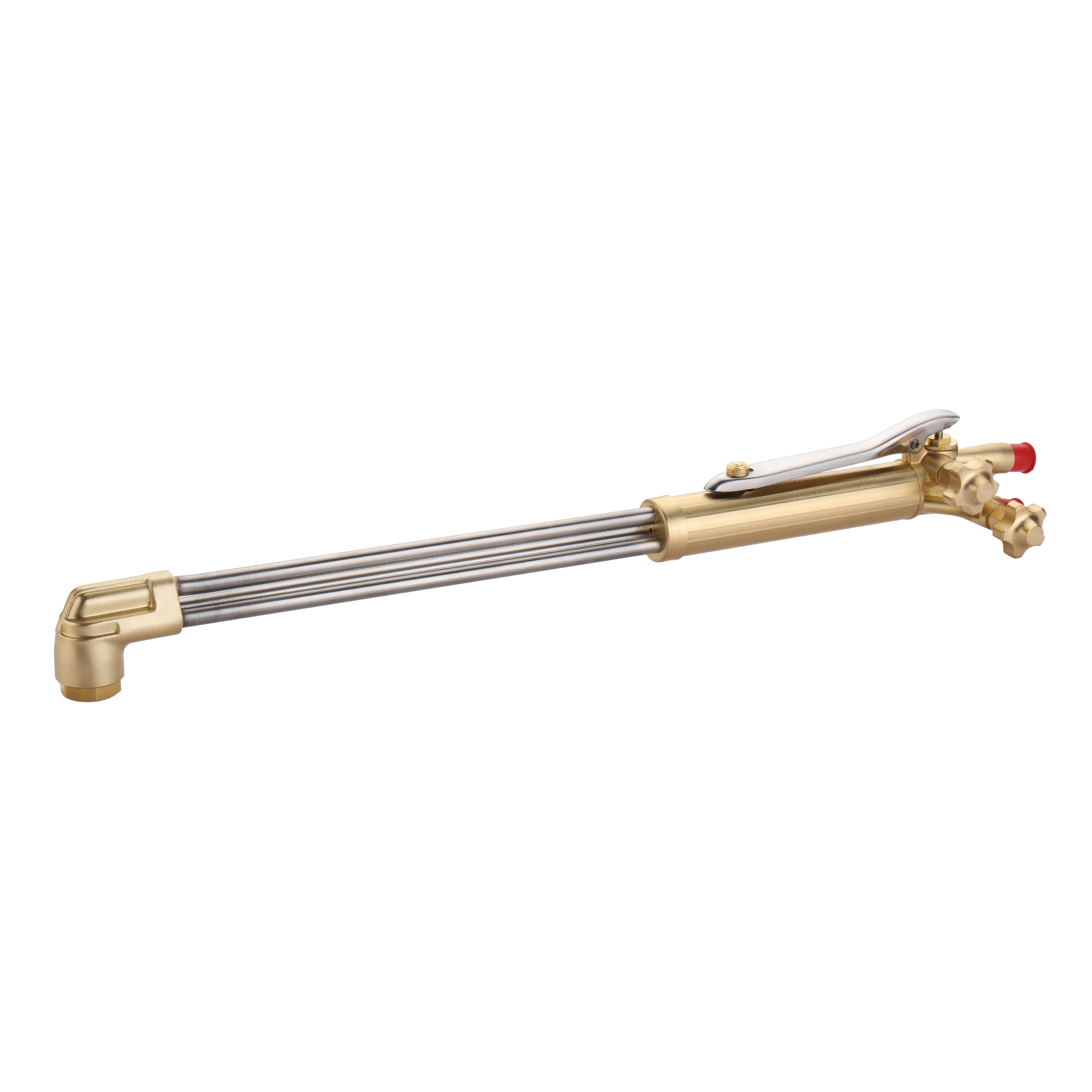
Torch angle dictates exactly how the pre-heat flames and the high-velocity oxygen jet penetrate the material. A perpendicular 90-degree angle remains the absolute baseline requirement for standard, thick-plate straight cuts. This vertical orientation ensures the oxygen jet clears the kerf efficiently and pushes the molten slag straight down. However, specific applications require intentional directional angling. Angling the cutting torch forward into the cut at a 30-40 degree lead angle helps pre-heat the kerf on thicker sections, allowing the reaction to initiate faster. Trailing angles, where the tip points back toward the completed cut, are generally reserved for specific piercing routines or gouging applications where material displacement is prioritized over a clean, square sever.
When setting up for a standard straight cut on mild steel, operators should follow these positioning rules:
Square the tip exactly 90 degrees to the plate surface using a machinist square for mechanized setups.
Adjust the standoff distance so the inner pre-heat cones sit just above the plate surface, typically 1/8 to 3/16 of an inch.
Maintain this exact angle and standoff distance throughout the entire length of the cut to prevent kerf divergence.
Bevel cuts severely complicate the thermal dynamics of the cutting process. Increasing the torch angle to create a 45-degree bevel physically increases the effective material thickness the oxygen stream must penetrate. A 1-inch plate cut at a 45-degree angle presents a 1.41-inch cross-section to the oxygen jet. This physical reality necessitates significantly slower travel speeds and higher oxygen pressures. Auxiliary pre-heating becomes absolutely necessary for steep bevels or heavy plate. Running an extra pre-heating oxy-fuel torch directly in front of the primary cutting head improves cutting speed significantly by raising the base metal temperature before the cutting oxygen hits it. This dual-torch technique yields up to a 100% speed improvement at steep 70-degree angles, and up to 50% at other acute angles, preventing the cut from failing halfway through the plate.
Manual cutting introduces inherent human inconsistencies that degrade cut quality. Grip fatigue, micro-stutters, and uneven breathing disrupt the fluid motion required for a clean, continuous cut. Mechanized track burners, pipe bevelers, or CNC profile machines eliminate these variables entirely, providing controlled, constant travel speeds and rigid standoff distances. Mitigating inconsistencies in manual operations requires strict physical technique. Operators must maintain a steady grip, lock their elbows, and use full body positioning to manage their pace rather than just moving their wrists. Implementing physical guides, straight edges, or using standoff wheels helps mimic mechanized consistency, stabilizes the torch height, and prevents the tip from dipping into the molten puddle.
Hardware selection directly impacts the fluid dynamics of the gas streams. The cutting nozzle design must perfectly match the specific fuel gas being used on the shop floor. Acetylene, propane, natural gas, and propylene possess vastly differing flame temperatures, heat distribution profiles, and oxygen-to-fuel ratios. Using a two-piece propane nozzle with acetylene disrupts the flame chemistry, causing backfires and poor pre-heat times. Furthermore, operators must strictly correlate the nozzle orifice size with the steel plate thickness. An oversized nozzle wastes massive amounts of gas, melts the top edges, and creates a wide, sloppy kerf. An undersized nozzle lacks the oxygen volume and kinetic energy to clear the molten slag from the bottom of the kerf, resulting in incomplete cuts and heavy dross.
Fuel Gas Type | Nozzle Design Requirement | Pre-heat Characteristics |
|---|---|---|
Acetylene | One-piece, flat face, drilled orifices | Intense, concentrated heat, fast piercing |
Propane / LPG | Two-piece, splined insert, recessed tip | Broad heat spread, excellent for beveling |
Natural Gas | Two-piece, deep recess, heavy pre-heat flutes | Slower start times, very clean cut face |
Equipment condition dictates baseline performance. Spatter buildup, carbon fouling, or damaged nozzle flutes instantly distort the high-velocity oxygen jet. A distorted jet creates an irregular kerf, uneven drag lines, and pushes slag to one side of the cut. Once the nozzle is physically compromised by a tip strike or heavy spatter, adjustments to speed and angle become completely useless. Regular inspection and cleaning of the nozzle orifices using proper tip cleaners are mandatory to maintain cut quality and prevent turbulent gas flow. If a tip cleaner does not slide smoothly through the central cutting orifice, the nozzle must be discarded and replaced immediately.
Oxy-fuel cutting has distinct physical limitations regarding total heat input. Small surface areas suffer from rapid thermal saturation because the heat from the pre-heat flames has nowhere to dissipate. Cutting small parts, narrow strips, or closely nested profiles results in poor quality, often referred to on the shop floor as garbage cuts. The material lacks the thermal mass to absorb and distribute the intense heat, causing severe warping, bowing, and edge melting regardless of perfect torch settings. When thermal distortion risks exceed the capabilities of the process, alternative technologies like high-definition plasma or fiber laser cutting become necessary to maintain dimensional accuracy on small components.
To mitigate distortion when cutting smaller profiles with oxy-fuel, programmers and operators can utilize specific techniques:
Implement water tables or water sprays to rapidly quench the plate behind the cut.
Use skip-cutting or chain-cutting techniques to distribute heat evenly across the entire plate.
Leave small tabs on nested parts to keep them anchored to the main skeleton until cooling is complete.
Reduce pre-heat flame intensity to the absolute minimum required to sustain the cut.
Consistent quality across multiple shifts requires standardized, documented procedures. Facilities should implement strict parameter audits to document and enforce speed, pressure, and angle charts. These charts must be prominently displayed and categorized by material thickness, cut type, and fuel type. Evaluating the return on investment involves comparing operator training against equipment upgrades. Upskilling manual operators in steady-hand pacing and proper setup improves baseline quality. However, investing in semi-automated cutting carriages or track burners eliminates human variables in speed and angle entirely, ensuring repeatable precision and drastically reducing the hours spent on post-cut grinding.
Gas cutting quality relies on a strict mathematical relationship between travel speed, torch angle, and oxygen dynamics. Failure to control even one of these variables inevitably cascades into costly mechanical rework, scrapped parts, and wasted consumables. Procurement and engineering teams should prioritize mechanized cutting carriages and high-quality, gas-specific nozzles before attempting to troubleshoot operator technique. To immediately improve cut quality and reduce rework on the shop floor, implement the following actions:
Conduct a baseline audit of current gas pressures, oxygen purity levels, and regulator conditions at all cutting stations.
Standardize nozzle selection by removing all mismatched or damaged tips from the shop floor and issuing new, gas-specific consumables.
Implement a time-study on post-cut grinding to identify which specific thicknesses or operators are generating the most rework.
Deploy mechanized track burners for all straight-line cuts over 24 inches to eliminate manual speed variations.
A: Moving too fast narrows the kerf and causes incomplete penetration. Moving too slow widens the kerf and causes excessive top-edge melting.
A: Use 90 degrees for standard straight cuts. A slight forward angle of 5-10 degrees assists thinner materials by pushing slag ahead. A 30-40 degree lead angle helps pre-heat thicker sections.
A: Heavy, fused slag is typically caused by traveling too slowly, using an oversized cutting nozzle, or applying insufficient oxygen cutting pressure.
A: Purity below 99.5% drastically reduces the oxidation reaction rate. This forces the operator to slow down and results in rough, heavily drossed cuts.
A: No. A damaged nozzle distorts the cutting oxygen stream. Angling the torch will only exacerbate the irregular kerf and chaotic gas flow dynamics.
A: Small parts lack the mass to dissipate the high heat input of the oxy-fuel process. This leads to thermal saturation and unavoidable distortion, especially when cuts are tightly nested.